


Description
Description
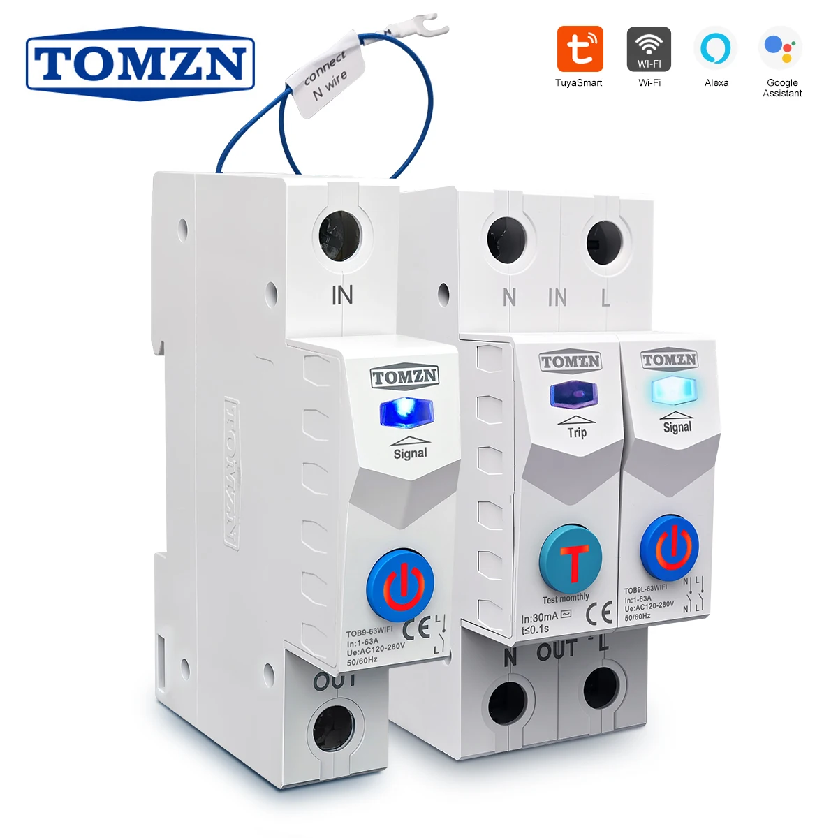
TOB9L-63WIFI 2P can cut off L and N both,
With leakage protection, NO temperature control.
TOB9-63WIFI 1P Can only cut off L,
NO leakage protection, With temperature control.
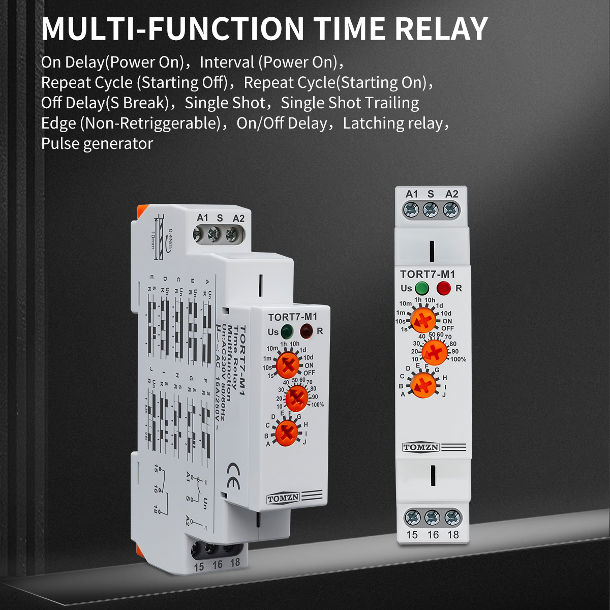
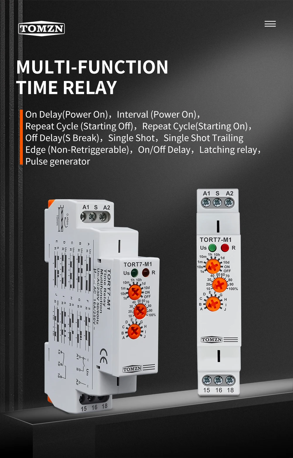
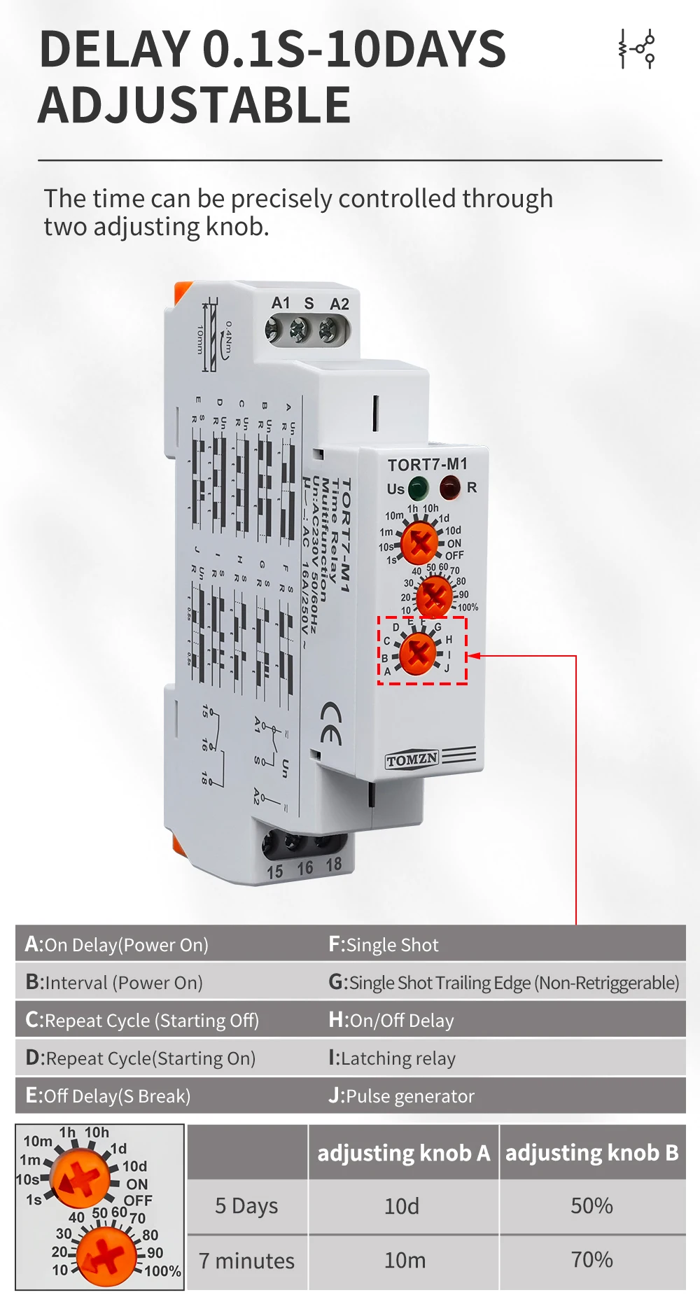
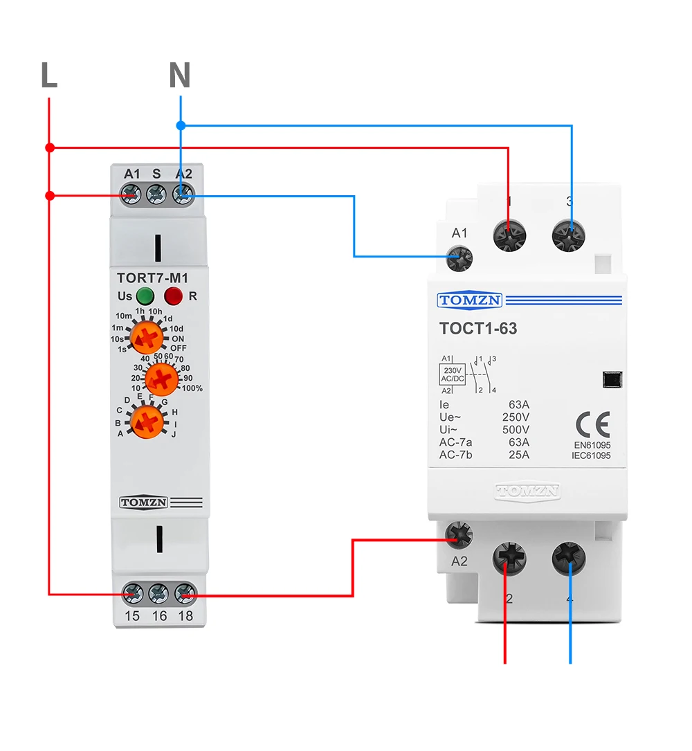
TORT7-M1 10 in 1 Multi-function time relay
1.General
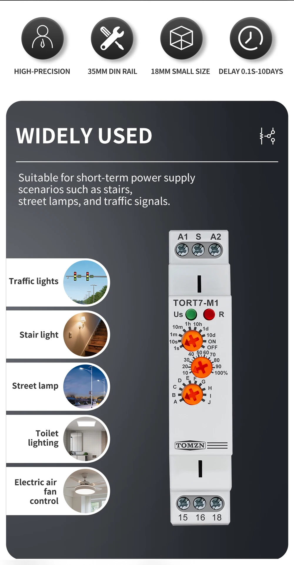
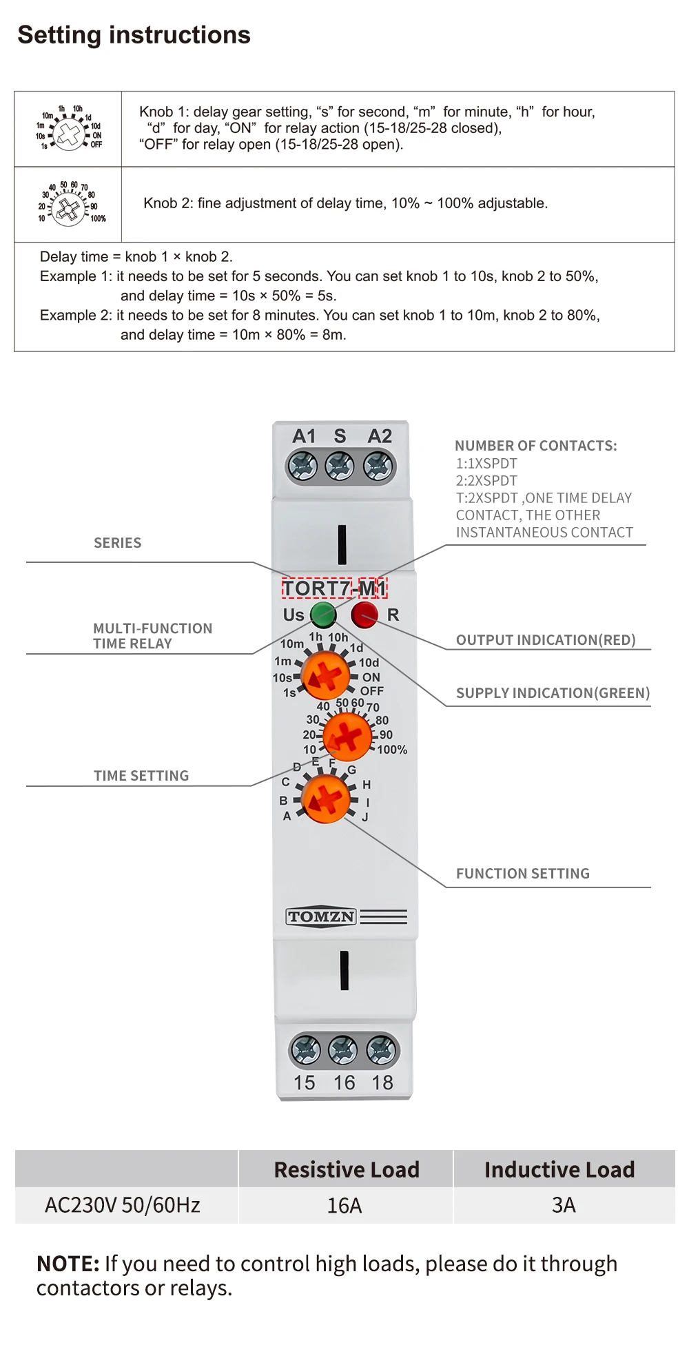
TORT7-M1 is a versatile solution for controlling electrical appliances, lighting, heating, motors, pumps, and fans. It offers 10 timing functions and 10 adjustable time ranges, from 0.1 seconds to 10 days, all easily set via user-friendly rotary switches. Supporting multi-voltage applications, this compact DIN rail module provides reliable automation with a clear LED status indicator for seamless integration into various control systems.
2.Technical Data
Model: TORT7-M1
Functions:
- 5 time functions controlled by supply voltage
- 4 time functions controlled by control input
- 1 function of latching relay
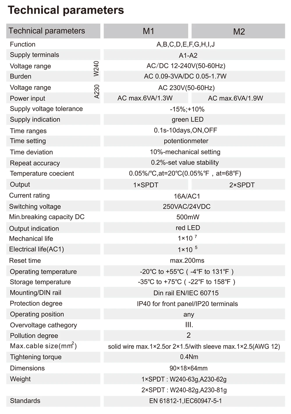
Voltage range: AC230V (50/60Hz)
Power input: AC max.6VA/1.3W
Supply voltage tolerance: -15%;+10%
Time ranges: 0.1s-10days,ON,OFF
Time setting: Potentionmeter
Time deviation: 10%-mechanical setting
Repeat accuracy: 0.2%-set value stability
Temperature coecient: 0.05%/C,at=20°C(0.05%,at=68℉)
Output: 1xSPDT
Current rating: 16A/AC1
Switching voltage: 250VAC
Min.breaking capacity DC: 500mW
Supply indication: green LED
Output indication: red LED
Mechanical life: 1×10⁷
Electrical life: 1×10⁵
Reset time: max.200ms
Operating temperature: -20℃ to +55℃
Storage temperature: -35°C to +75°C
Mounting/DIN rail: Din rail EN/IEC 60715
Protection degree: IP40 for front panel/IP20 terminals
Operating position: any
Overvoltage cathegory: III.
Pollution degree: 2
Max.cable size(mm2): solid wire max.1×2.5 or 2×1.5/with sleeve max.1×2.5(AWG 12)
Tightening torque: 0.4Nm
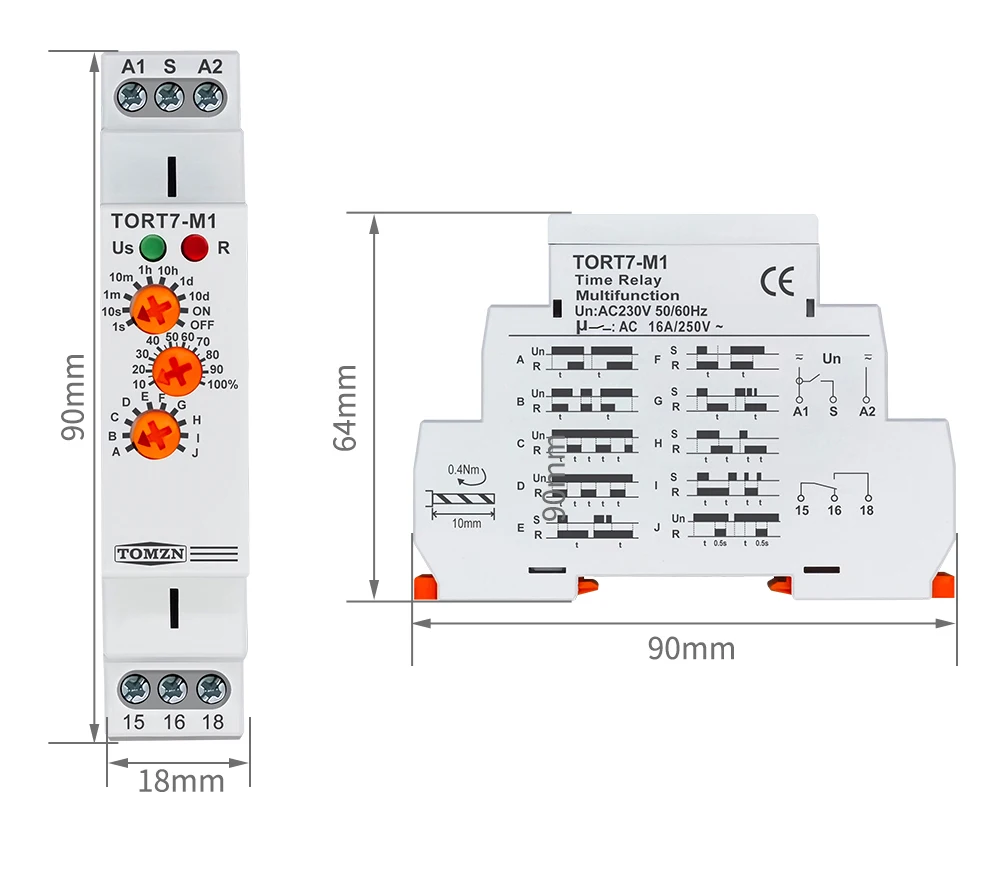
Dimensions: 90x18x64mm
Standards: EN 61812-1,EC60947-5-1
3.Function Features
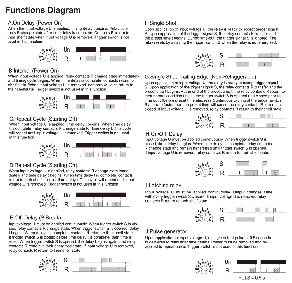
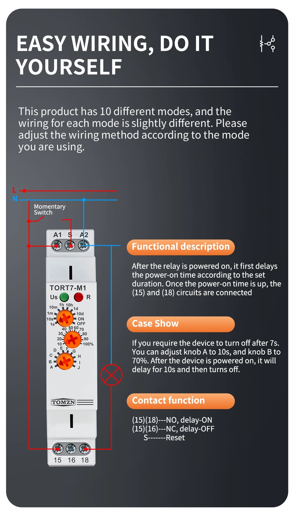
A:On Delay (Power On)
When the input voltage U is applied, timing delay t begins. Relay contacts R change state after time delay is complete. Contacts R return to their shelf state when input voltage U is removed. Trigger switch is not used in this function.
B:Interval(Power On)
When input voltage U is applied, relay contacts R change state immediately and timing cycle begins. When time delay is complete, contacts return to shelf state, When input voltage U is removed contacts will also return to their shelf state.Trigger switch is not used in this function.
C:Repeat Cycle (Starting Off)
When input voltage U is applied, lime delay t begins. When time delay t is complete, relay contacts R change state for time delay t. This cycle will repeat until input voltage U is removed. Trigger switch is not used in this function.
D:Repeat Cycle (Starting On)
When input voltage U is applied, relay contacts R change state immediately and time delay t begins.When time delay t is complete, contacts return to their shelf state for time delay t, This cycle will repeat until input voltage U is removed, Trigger switch is not used in this function.
E:Off Delay (S Break)
Input voltage U must be applied continuously, When trigger switch S is closed, relay contacts R change state, When trigger switch S is opened, delay t begins, when delay t is complete, contacts R return to their shelf state.If trigger switch S is closed before time delay t is complete, then time is reset, When trigger switch S is opened, the delay begins again, and relay contacts R remain in their energized state, lf input voltage U is removed.relay contacts R return to their shelf state.
F:Single Shot
Upon application of input voltage U, the relay is ready to accept trigger signal S. Upon application of the trigger signal S, the relay contacts R transfer and the preset time t begins. During time-out, the trigger signal S is ignored, The relay resets by applying the trigger switch S when the relay is not energized.
G:Single Shot Trailing Edge (Non-Retriggerable)
Upon application of input voltage U, the relay is ready to accept trigger signal S. Upon application of the trigger signal S, the relay contacts R transfer and the preset time t begins. At the end of the preset time t, the relay contacts R return to their normal condition unless the trigger switch S is opened and closed prior to time out t (before preset time elapses). Continuous cycling of the trigger switch S at a rate faster than the preset time will cause the relay contacts R to remain closed. lf input voltage U is removed, relay contacts R return to their shelf state.
H:On/Off Delay
Input voltage U must be applied continuously. When trigger switch S is closed, time delay t begins. When time delay t is complete, relay contacts R change state and remain transferred until trigger switch S is opened.If input voltage U is removed, relay contacts R return to their shelf state
Note:To ensure reliable operation, install this electrical device in a standard cabinet away from interference sources, using protective measures and verifying system compatibility.
I:Latching relay
Input voltage U must be applied continuously. Output changes state with every trigger switch S closure. lf input voltage U is removed,relay contacts R return to their shelf state.
J:Pulse generator
Upon application of input voltage U, a single output pulse of 0.5 seconds is delivered to relay after time delay t. Power must be removed and re-applied to repeat pulse. Trigger switch is not used in this function.
Reviews
There are no reviews yet.